Abstract
This paper summarizes the exist problems of conventional capacitor switching switch, designed the composite switch based on MCU, described in detail of its hardware and software design. It also describes it’s applications in low-voltage reactive power compensation. which can not only increase the number of switching capacitor banks, and improve power factor and power quality.
Keywords: composite switch; capacitor switching switch; reactive power compensation
Reactive power compensation is a basic requirement of power system operation, in order to achieve reactive power balance, must be compensated for various load’s requirement. Reactive power compensation methods includes condenser compensation, capacitor banks and others. The most effective and easy to implement way is local compensation near the load. Since reactive power compensation attached to the power system through input and removal power capacitors to achieve the compensation effect, the performance of capacitor switching elements play a key role for the quality and stability of the whole system. At present, reactive power compensation products generally use AC contactor or triac as the switching element, inevitably there are long-term safe operation problems includes power consumption, temperature rise and harmonic(referred as "electrical pollution"), which effects equipment’s life and reliability of the entire apparatus, and even affect the normal operation of the entire power grid. This composite switch based on MCU is an ideal switching switch. Here detailing introduce the hardware and software design and it’s application in
low-power reactive compensation.
1. Main existed problems of conventional capacitor switching switch
main problems are:
The SCR or high-power solid-state relay as a non-contact switch while having features of fast response, minor surge, but there is a large power consumption that leads severe fever when high working current, it needs to add heat sink or even forced refrigeration. This will not only increase the volume of compensation device, but also increase cost.
AC contactor dedicated to the switched capacitor connects current limiting resistor to the primary circuit, has the feature of lower costs, reduced power consumption, but there is still a large inrush current having greater impact to the power grid or capacitor.
(compared with dry limiting reactors using unsaturated polyester resin casting molding)
2. composite switch based on MCU
Composite switch using intelligent control technology and the latest electronic components, is suitable for reactive power compensation of AC 380V. The basic principle is parallel connection of AC contactor and SCR. Composite switch has the advantages of zero-cross switch when switching on or off, but also no power consumption during normal contactor on. Besides has features of intelligent monitoring, self-diagnostic, low power consumption, no harmonics and comprehensive fault protections includes lack-phase protection, no-load protection. It’s Control signal use + 12V. Hardware block diagram shown in Figure 1. It uses 80C196KB microcontroller which is particularly suitable for high real-time requirements of the control system and selected Motorola's zero trigger control chip MOC3083. Its control circuit shown in Figure 2. Since MOC3083 is a current-driven, requiring more than 5mA. In order to reliably drive, use Darlington MC1413 in the system, and design l0mA as driven current.
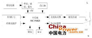
Figure 1 hardware block diagram
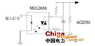
Figure 2 optical isolation control circuit diagram
In the process of switching capacitor, for contact-type switch, tend to have strong electric arc which will damage the contacts, result in poor contact, or even molten the contacts; for non-contact type switch such as SCR and high-power solid-state relays, because of its large power consumption, heat dissipation problem is particularly prominent. For the above, composite switch design the delay circuit. When switching on, turn on thyristor and delay 2 to 3 cycles, and then switch on contactor and turn off the thyristor, so the load current goes through the contactor; when switching off, turn off the contactor first, switch off the thyristor after delayed 2 to 3 cycles. Thus fundamentally solved to the surge and electric arc when turning on and off contactor, and eliminates heat dissipation problem for non-contact switch. It not only greatly extend the life of the switch, but also improves system reliability. Software program flow shown in Figure 3.
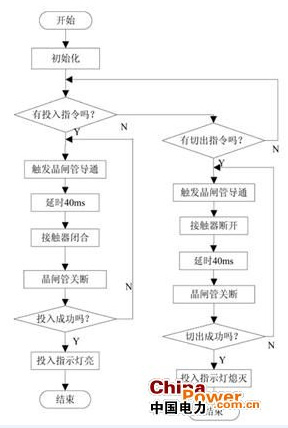
Figure 3 main flowchart
In order to achieve the desired operating conditions, strict timing of on-off is required. Assuming that high for command on and low for command off, signals of its state shown in Figure 4
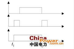
Figure 4 composite switch state diagram
3. characteristics
Composite switch has the following characteristics:
• zero-cross on-off;
• Low power consumption;
• No reactor series connected;
• optical isolation of input signal and switch;
• directly work with any reactive power compensation controller
• Built-in control power;
• status indicator;
• high interference ability, reliable for high-capacity capacitor.
4. Application in Reactive Power Compensation
Most end of the low-voltage grid in the grid, thus compensating low voltage reactive compensation load is the key to the power grid. Improve low-voltage compensation, not only can reduce the pressure on the level of compensation grid, but also improve the utilization of the power distribution transformers, power factor and voltage improve user quality, and reduce energy losses. Low-voltage compensation on the user and the electricity sector are favorable.
The goal of Low-voltage reactive compensation to achieve balance of reactive power, commonly using in three ways: random compensation, transformer compensation, tracking compensation. Composite switch has two type independent and three-phase.The wiring diagram shown in Figure 5.
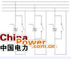
(A) wiring diagram of independent compensation
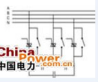
(B)wiring diagram of three-phase compensation
Figure 5 composite switch switching capacitor
As a result of using composite switch, with low inrush current and no risk of stick, frequently on-off of capacitor can be achieved. Therefore we can improve the compensation accuracy by increasing the number of capacitor groups. In practice, by the precise control of switching controller, power factor can be maintained between 0.96 to 0.99.Composite switch not only improves reliability, but also improve power quality.
5.Conclusion
The innovation of this paper is composite switch based on MCU microprocessor has features of low consumption, less harmonic, long life, etc, which can replace contactor or SCR switch as an ideal product for switching capacitor, is widely used in the field of low-voltage reactive compensation. By increasing the number of capacitor banks, it can improve power factor, improve power quality. |